Miner assembly
Follow this step-by-step guide to assemble your Proto-MDK. It is recommended you stage your work materials and clear a table or desk of any clutter. Assembling in a clutter-free area will make installation smoother and prevent damage to components.
Note: This guide is provided as a courtesy to MDK Beta participants. Block Inc. is not responsible or liable for the use of these instructions.
-
Orient the chassis
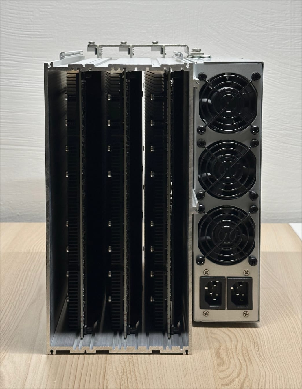
Rotate the chassis so the rear (with the three large open slots at the top) is facing you, as shown. Note, the sharp edges of the chassis may scratch surfaces.
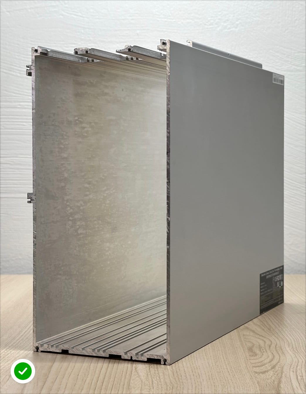 Rear of the chassis
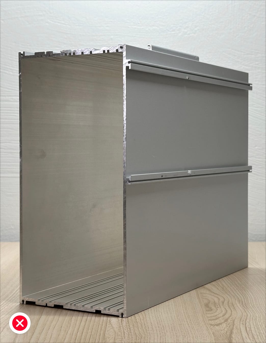 Front of the chassis
Required materials 1 x chassis
Front of the chassis
Required materials 1 x chassis -
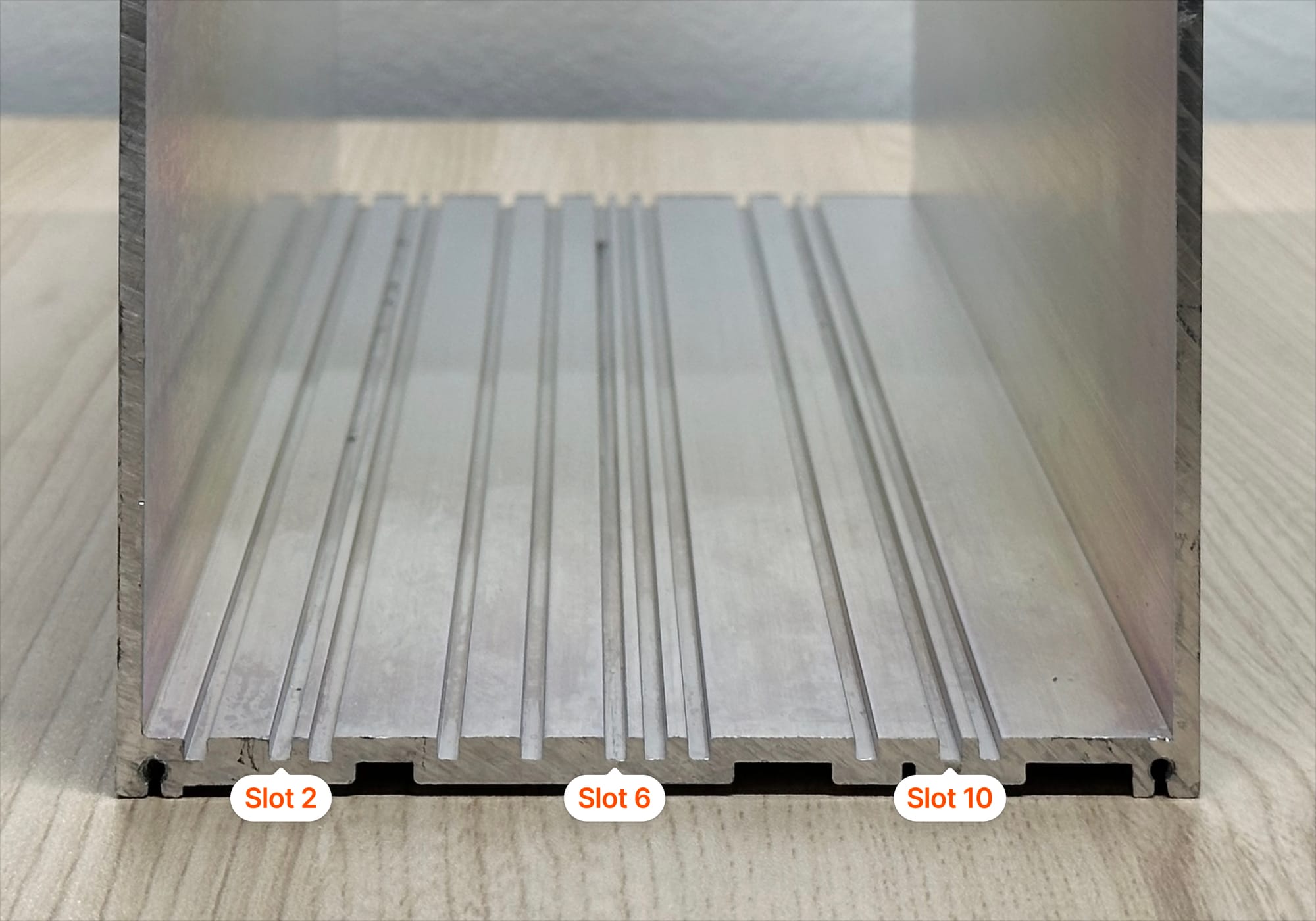
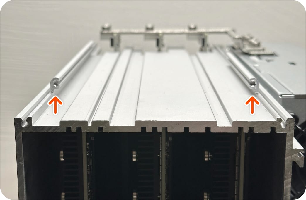
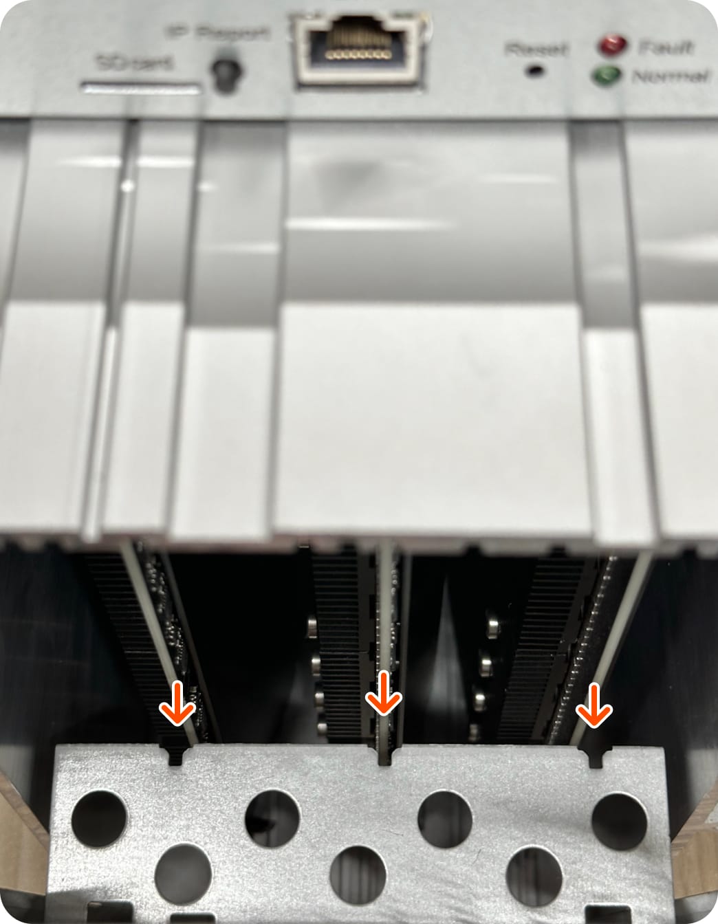
Locate the hashboard slots
Locate slots 2, 6, and 10 as shown below.
-
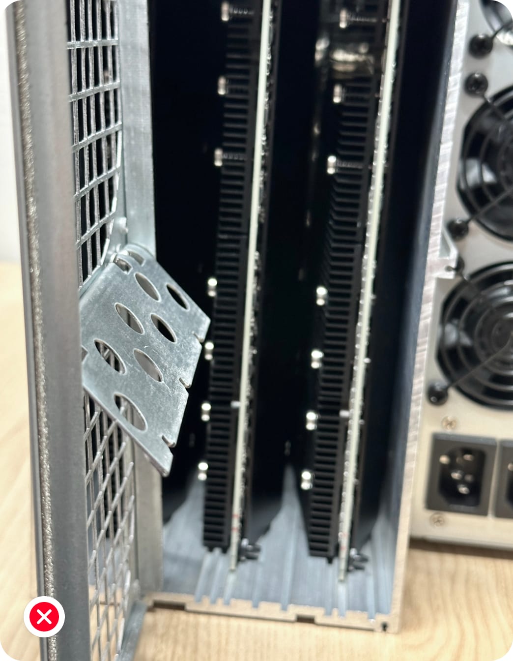
Insert the hashboards
Insert a hashboard into each designated slot with the baffle (flat surface) facing left and the heatsinks (fins) facing right. For proper alignment, ensure the top edge of the hashboard is inserted into the first slot of each top partition. Be careful not to damage the board edges or components.
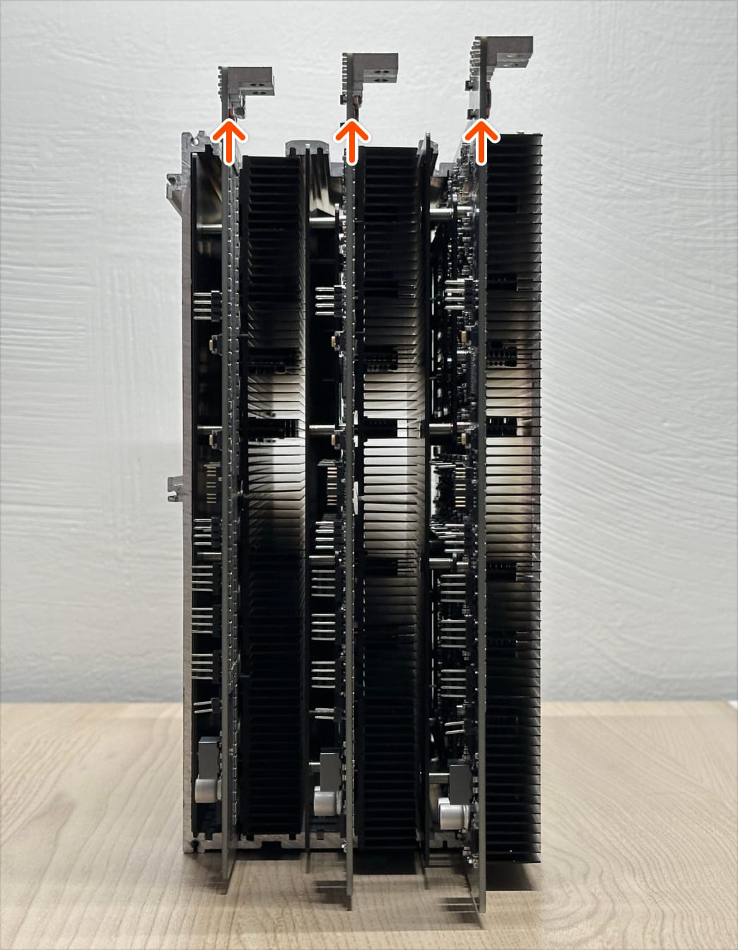 Proper hashboard orientation
Required materials 3 X hashboards
Proper hashboard orientation
Required materials 3 X hashboards -
Attach the power supply unit (PSU) to the chassis
Slide the PSU into the slots of the chassis. The upper tabs of the PSU will slide into the lower slot of the chassis. The lower tabs of the PSU will slide into the upper slots of the chassis.
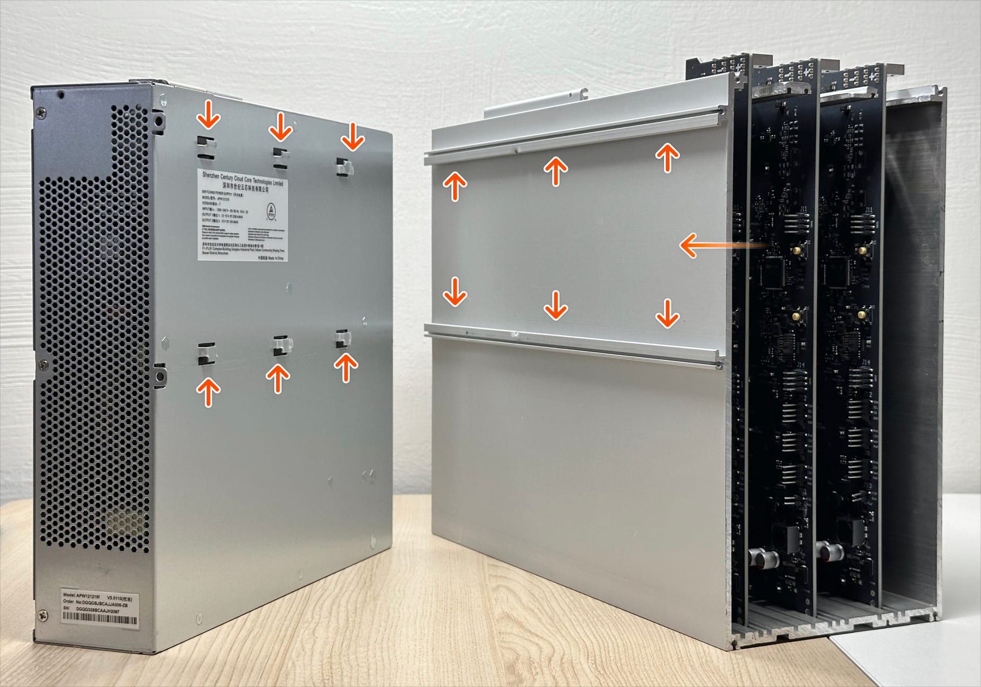 PSU tabs (left), chassis slots (right)
Required materials 1 × power supply unit
PSU tabs (left), chassis slots (right)
Required materials 1 × power supply unit -
Fasten the PSU to the chassis
Use one (1) M3 × 0.5mm x 8mm screw and torque to 0.45 N·m.
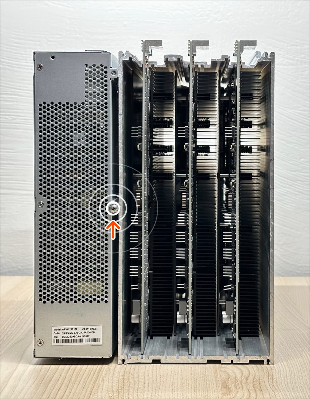 Required materials 1 × M3 × 0.5mm x 8mm
 -
Install the busbars
Install busbars onto to the PSU and hashboards using ten (10) M4 x 0.7mm x 8mm long screws. For proper alignment, ensure the hashboards are fully inserted. Partially tighten the screws with your fingers. You’ll completely tighten the screws after installing the fans.
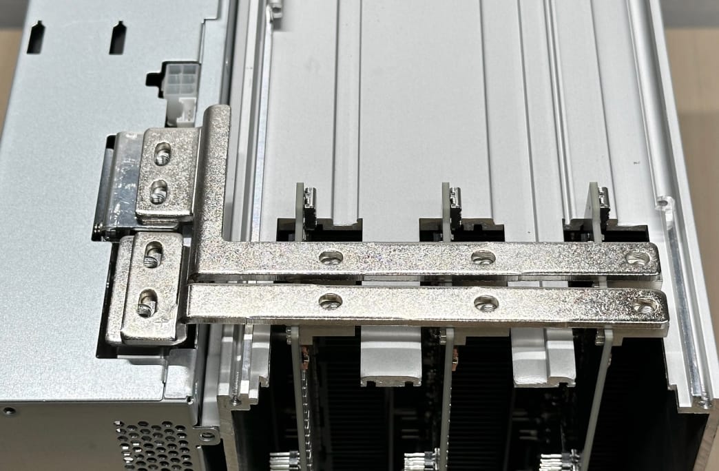 Busbar position
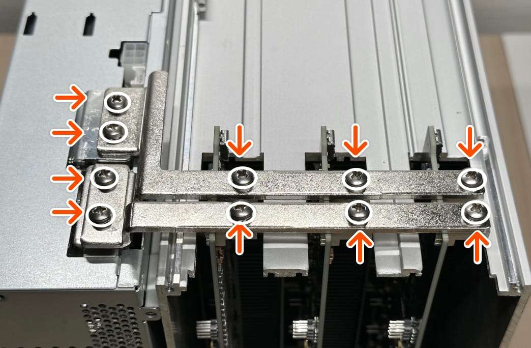 Screw installation
Required materials 2 × busbar • 10 × M4 × 0.7mm x 8mm
Screw installation
Required materials 2 × busbar • 10 × M4 × 0.7mm x 8mm -
Access the front of the chassis
Rotate the chassis so the front (no open slots at the top) faces you, as shown.
 Front of the chassis
-
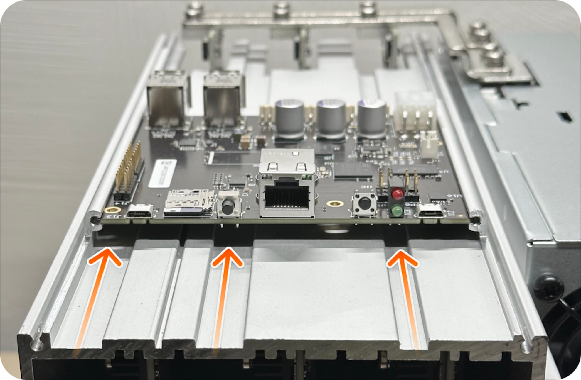
Install the control board
Slide the control board into the rails on top of the chassis. The Ethernet port and LEDs should face the front of the chassis and the USB-A connectors should face the rear of the chassis.
 Chassis rails for the control board
 Slide the control board back until full stop
Required materials 1 x control board
Slide the control board back until full stop
Required materials 1 x control board -
Install the microSD card
Insert the microSD card it into the control board microSD card slot.
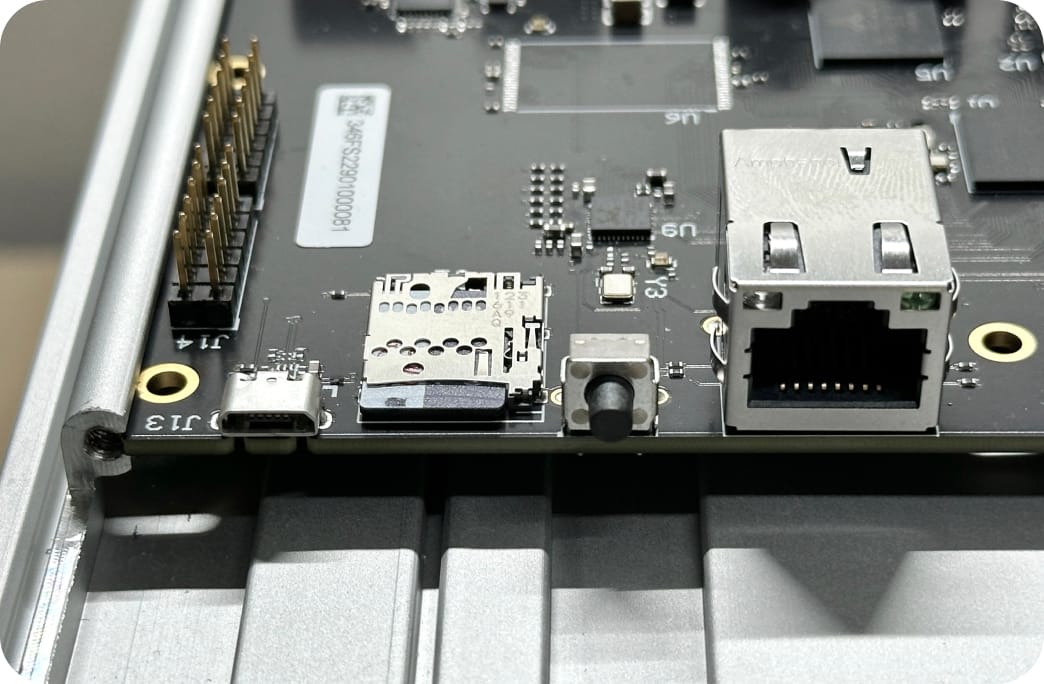 microSD card slot located to the left of Ethernet port
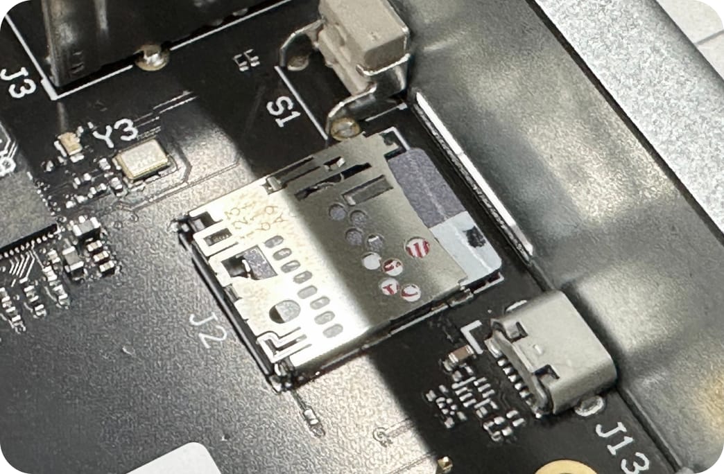 Ensure the microSD card is fully inserted into the card slot
Required materials 1 x 16GB (minimum) microSD card
Ensure the microSD card is fully inserted into the card slot
Required materials 1 x 16GB (minimum) microSD card -
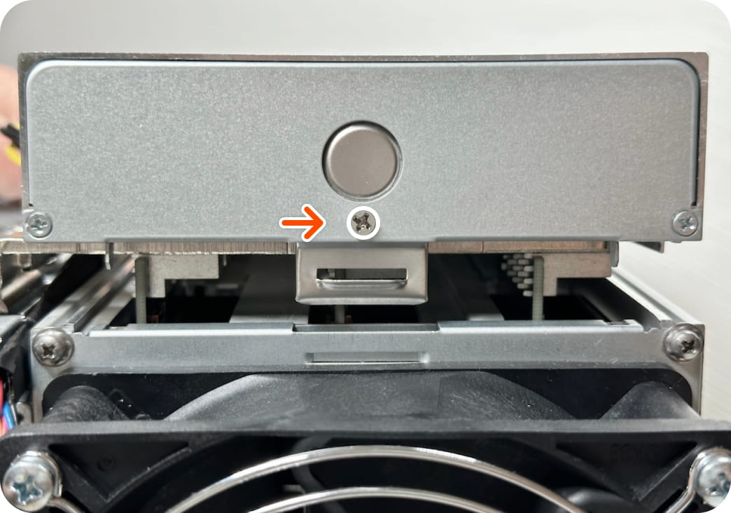
Install the faceplate
Fasten the faceplate to the chassis using two (2) M3 x 0.5mm x 6mm screws.
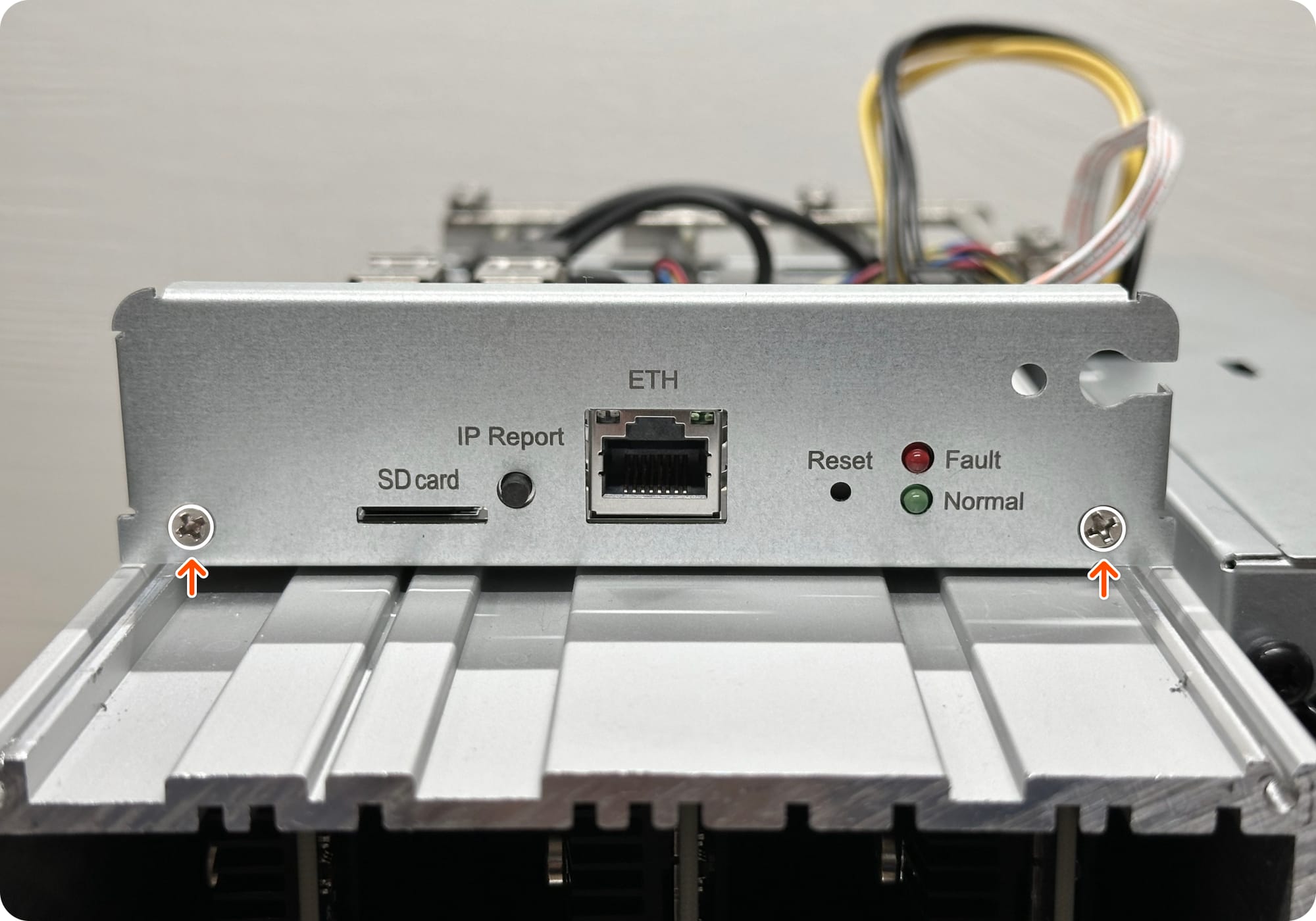 Faceplate fastener locations
Required materials 1 × faceplate • 2 × M3 x 0.5mm x 6mm
Faceplate fastener locations
Required materials 1 × faceplate • 2 × M3 x 0.5mm x 6mm -
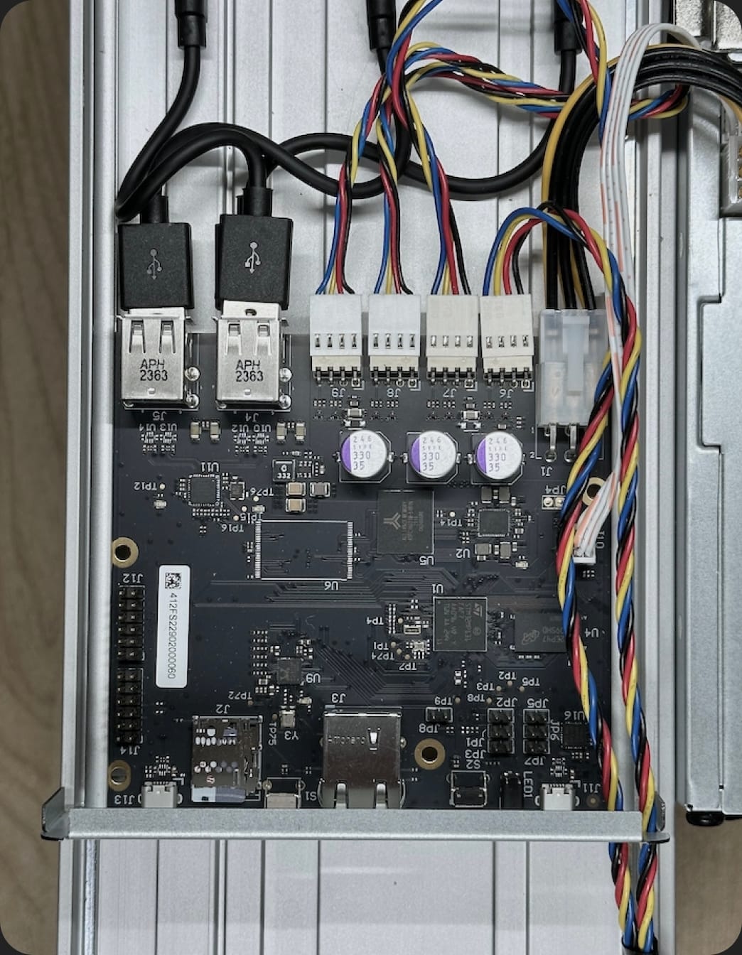
Connect the control board to the hashboard
Plug three (3) USB-A to USB-C cables from the control board into the hashboard connectors as shown. You can safely use any of the four available USB-A slots.
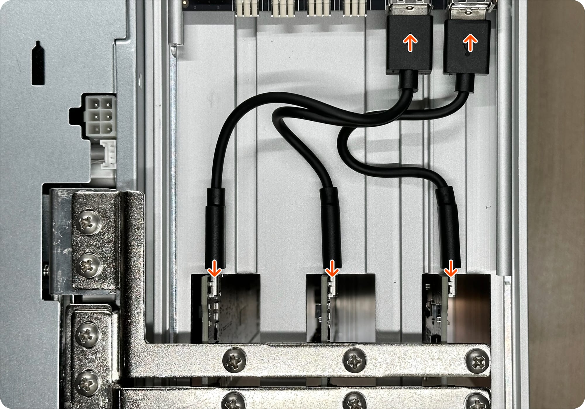 Required materials 3 × USB-A to USB-C, 15cm
 -
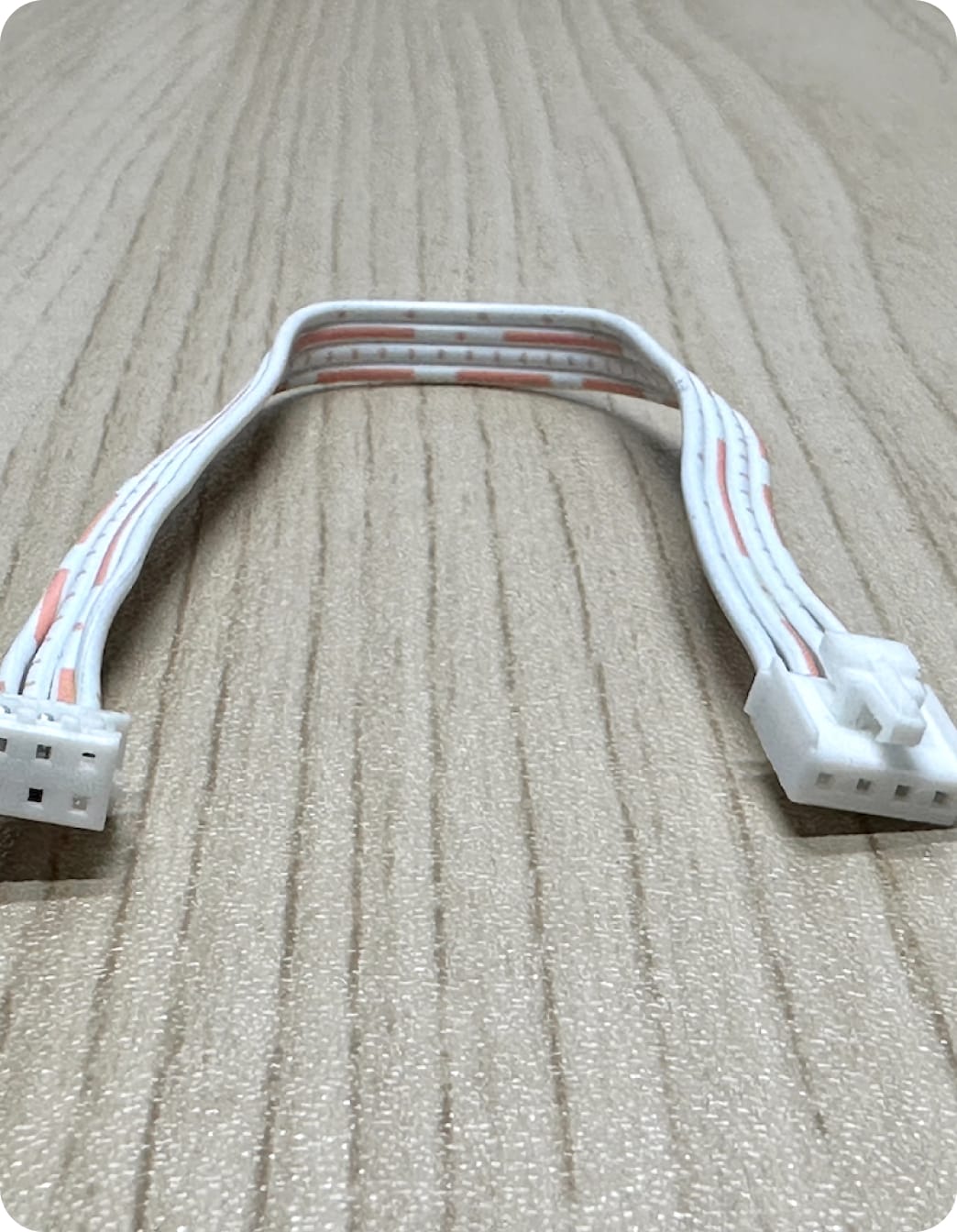
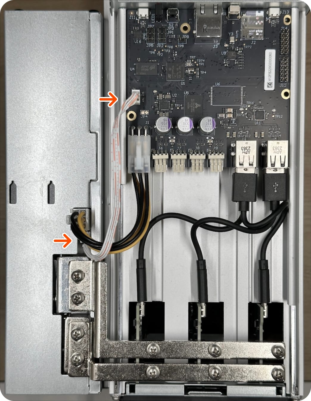
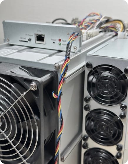
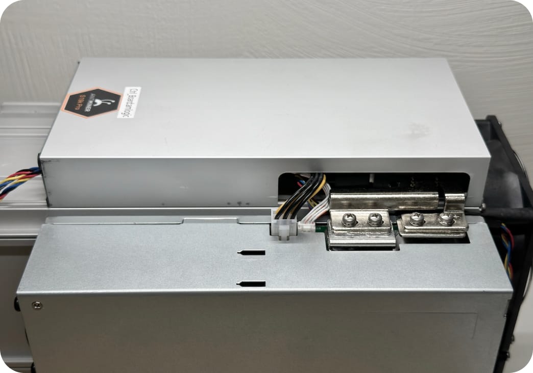
Install extension cable
Connect one (1) 6pin to 6pin extension cable from the control board to the PSU. Avoid applying excessive pressure to prevent damaging surrounding components. Note, the 6pin connector is orientation specific with the tab facing the PSU.
 Extension cable (6pin to 6pin)
 Proper cable routing
Required materials 1 × 6pin to 6pin cable
Proper cable routing
Required materials 1 × 6pin to 6pin cable -
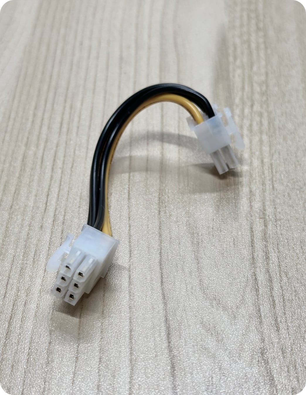
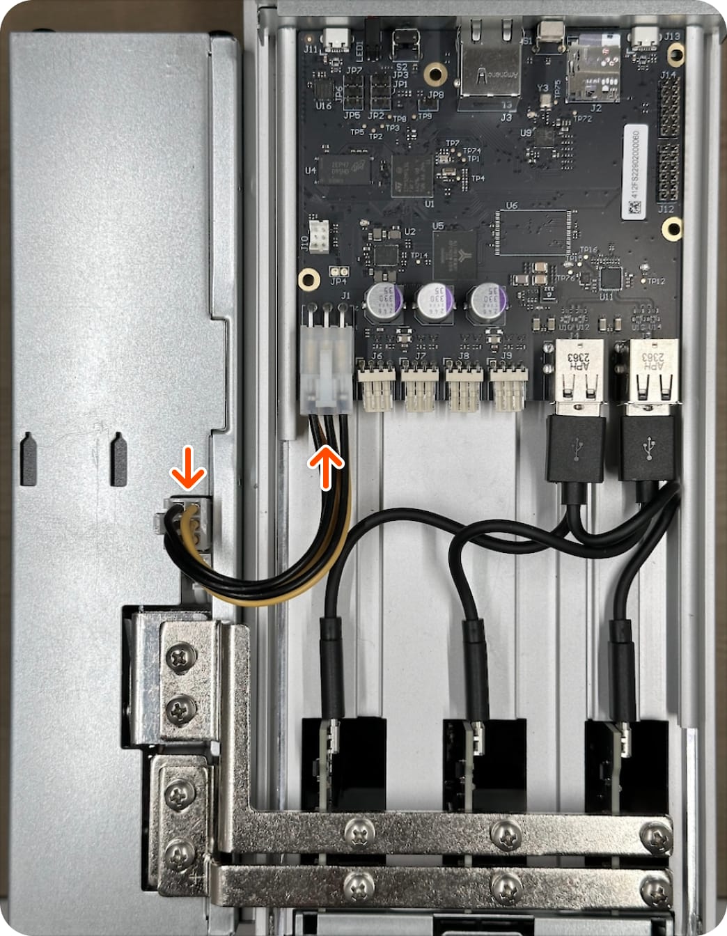
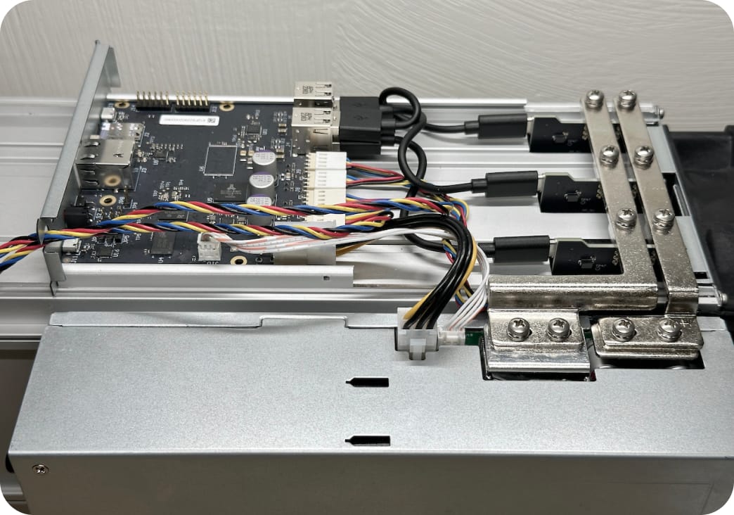
Install the voltage regulating cable
Connect one (1) 6pin to 4pin voltage regulating cable from the control board to the PSU, as shown. The 6pin tab should be inserted into the control board, and the 4pin connector to the PSU. Note, the 4pin connector is orientation specific with the tab facing the PSU.
 Voltage regulating cable (6pin to 4pin)
 Proper cable routing
-
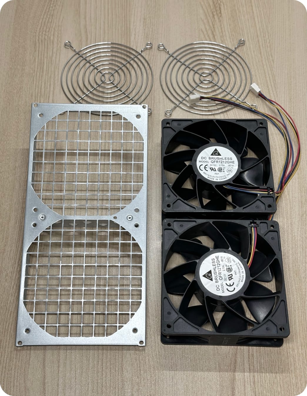
Assemble the rear fan module
Assemble the rear fan module, which includes the rear chassis mesh plate, two fans and two fan grills. Orient the mesh plate so the horizontal slot is at the top. Place the two fans with the fan grills onto the mesh plate and orient the fans so that the cables (which can be bound in parallel) are on the left. Connect the fans to the mesh plate using eight (8) M4 × 0.7mm x 42 mm long screws.
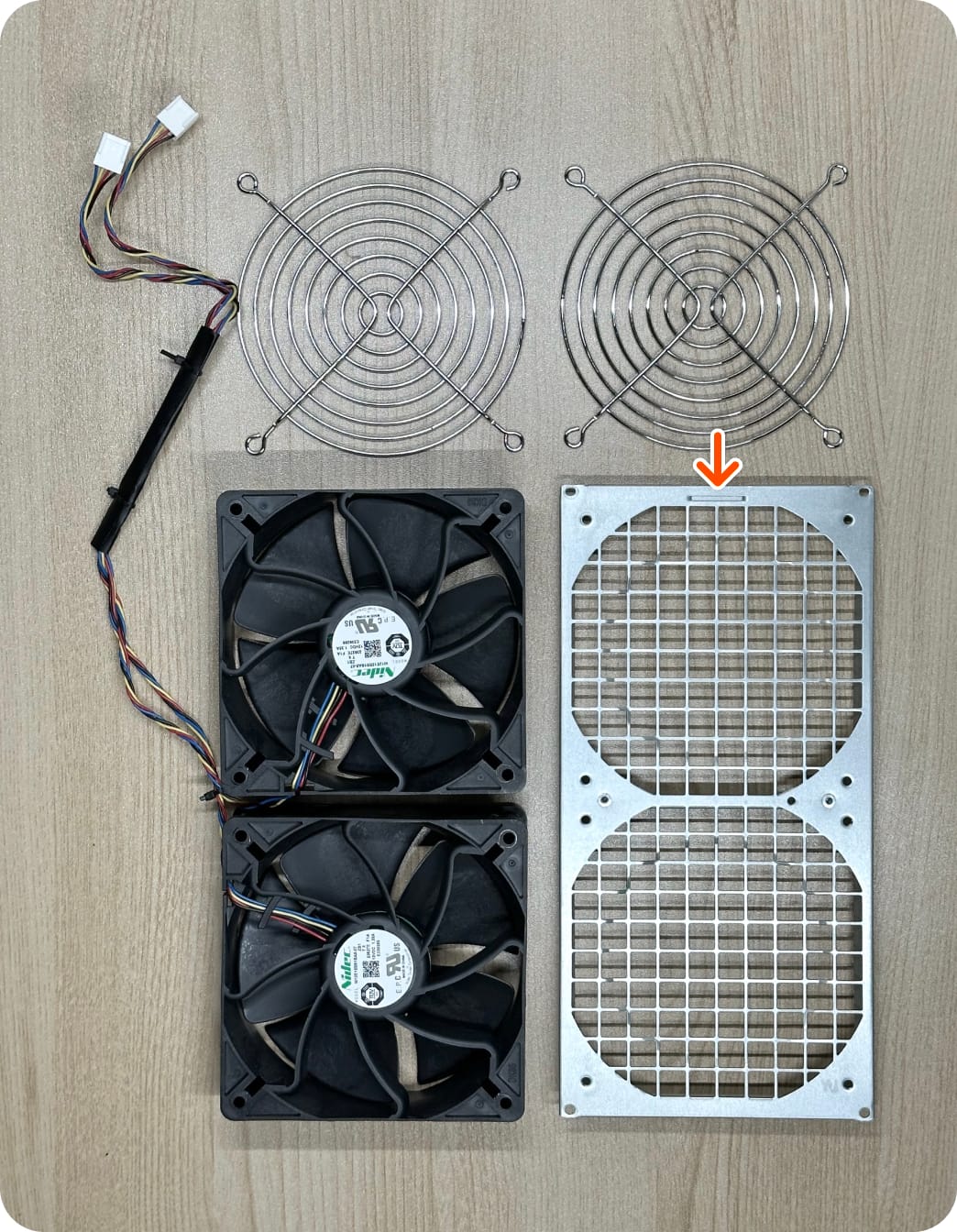 Rear fan components
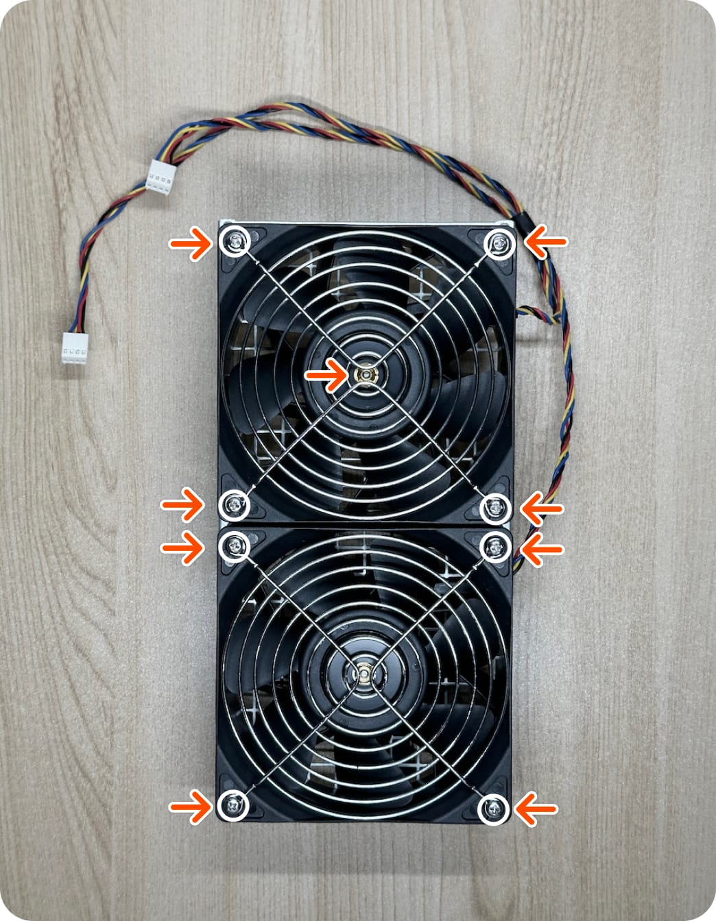
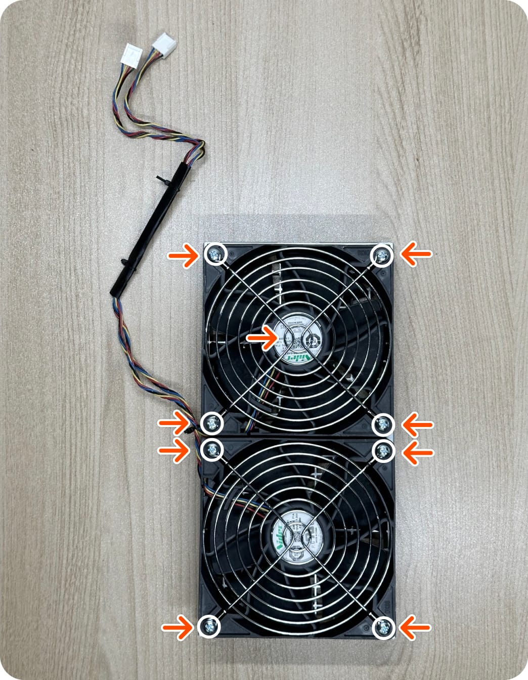 Fan screw locations — rear fan label should be facing you
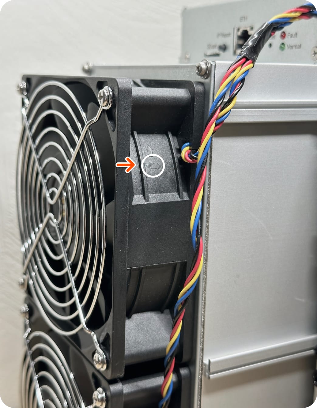
 Ensure that the the lower arrow is facing away from the chassis
-
Attach the rear fan to the chassis
Attach the rear fans to the chassis using four (4) M3 × 0.5mm x 8mm long screws.
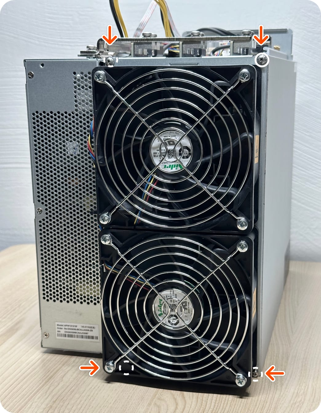 Rear fan attached to chassis
Required materials 4 × M3 x 0.5mm x 8mm
Rear fan attached to chassis
Required materials 4 × M3 x 0.5mm x 8mm -
Connect the rear fans to the control board
Route the rear fan cables through the channel beneath the busbars and plug the fan connectors into ports 3 and 4 as shown.
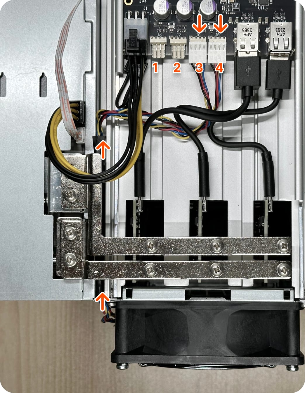 Proper cable routing
-
Assemble the front fan
Assemble the front fan, which includes the front chassis mesh plate, two fans and two fan grills. Place the two fans with the fan grills onto the mesh plate and orient the fans so that the cables (which can be bound in parallel) are on the right. Connect the fans to the mesh plate using eight (8) M4 × 0.7mm x 42 mm long screws.
 Front fan components
 Fan screw locations — front fan label should be facing away from you
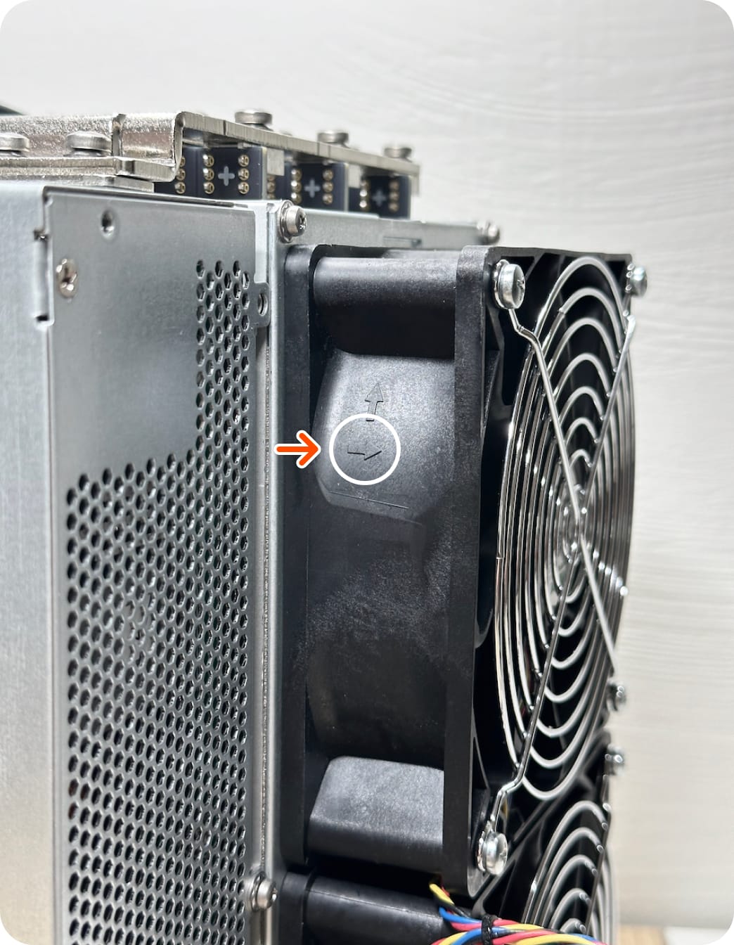
 Ensure that the lower arrow is facing toward the chassis
Required materials 8 × M4 x 0.7mm x 42mm
Ensure that the lower arrow is facing toward the chassis
Required materials 8 × M4 x 0.7mm x 42mm -
Line up the front fan module
Ensure fan mesh grill center divider slots line up with the vertical hashboards. If not, rotate fan mesh 180 degrees or double check the hashboards are in the correct slots. Depending on your chassis version, the center divider may be too long. You may contact a chassis supplier and request an S19j Pro fan mesh, or trim the length with a cutting tool.
 Align these slots to ensure a proper fit
 Avoid bending the center divider which can result in restricted airflow
-
Attach the front fan module
Attach front fan to the chassis using four (4) M 3× 0.5mm x 8mm long screws.
 Required materials 4 × M3 × 0.5mm x 8mm
 -
Route fan cables
Route the front fan cables through the front faceplate as shown. Use tape to bind fan wires, as needed.
 Cable routed through faceplate
 Proper cable routing
-
Torque busbar screws and check electrical connections
Torque all ten (10) M4 × 0.7mm × 8mm long screws to 1 N·m. Check all cable connections to ensure they're fully seated.
-
Install the top cover
Install the top cover as shown. The tab on the rear should engage fully with the chassis slot. The circular enclosure tab should be flush with the cover housing. If it is not, loosen or tighten the screw beneath the tab as needed.
 Required materials 1 × top cover
 -
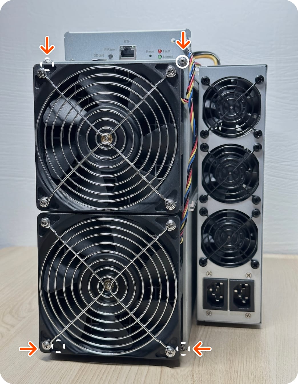
Connect the PSU cover to the chassis
Connect the PSU cover to the chassis using two (2) M3 × 0.5mm x 8mm long screws.
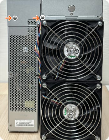 Final screws installation (rear view)
Required materials 2 × M3 x 0.5mm x 8mm
Final screws installation (rear view)
Required materials 2 × M3 x 0.5mm x 8mm -
Identify your miner on your network
Connect one end of the ethernet cable to the ethernet port on the control board and the other to your network router. Confirm the ethernet connector to the control board is illuminated. Connect your power cable female connector to the PSU and the male connector to a 200 - 240V AC outlet. Your miner will power on. Confirm that the LEDs flash from red to green. The flashing green LED will confirm the firmware upload was successful. To locate your miner's hostname or IP address, use a network discovery tool of your choice. We recommend Nmap, a free cross-platform tool you can download here. Identify your Proto-MDK on your network by:
- Recommended: miner hostname (proto-miner-last 4 digits of mac address)
- From terminal, run arp -a to find the IPv4 address associated to your MDK mac address
Populate the hostname or ip address into a browser search bar and hit enter. You will be taken to your Proto-MDK dashboard.
Enclosure
Control board
Before proceeding, document the control board's 12-digit MAC address and 16-digit serial number found on labels of your control board.
Firmware
Beta participants will receive a pre-flashed microSD card. The Proto team will contact users to update to the latest version.
microSD installation
Fans
Top cover
Miner discovery
Your Proto-MDK assembly is complete
Before you continue, check for missing screws or any damage that may have occurred during assembly as it may affect your miner’s performance. If you encountered damage to any of the Proto supplied components (e.g. controller board, hashboards, microSD card — contact support at mining.support@block.xyz ).